

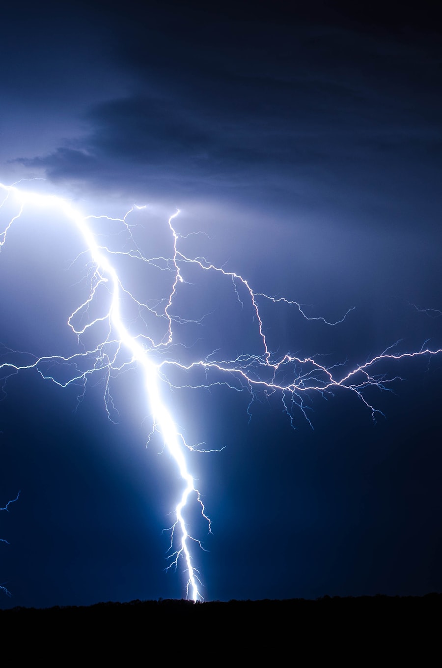
Step 1 — Charge Separation in the Storm Cloud
Lightning begins long before the visible flash. Inside a developing cumulonimbus (thundercloud), violent vertical air currents carry water droplets, ice crystals and hailstones at high velocities. As these particles collide, a process called charge separation occurs: smaller ice particles acquire a positive charge and are carried upward by updrafts; larger graupel (ice pellets) acquire a negative charge and remain in the lower portions of the cloud.
The result is a cloud with a strongly negative charge concentration at its base — typically carrying a charge of −5 to −20 Coulombs — and a weakly positive charge at its top. This charge configuration creates an electric field that extends downward to the earth's surface below the cloud. In response, the normally negatively charged ground surface directly below becomes positively charged through electrostatic induction.
Step 2 — The Stepped Leader
As the negative charge at the cloud base builds, the electric field gradient between cloud and earth increases. When it approaches the breakdown strength of air — typically 1–3 MV/m in the turbulent, humid air of a storm — the discharge process initiates.
A channel of weakly ionised air called the stepped leader propagates downward from the cloud base. It advances in discrete steps of 10–100 metres, pausing for approximately 50 µs between steps while the channel recharges. The stepped leader is largely invisible to the naked eye — it carries only a few hundred amperes and moves at an average velocity of about 200,000 m/s.
As the stepped leader descends, it branches extensively, creating the characteristic tree-like structure of a lightning channel. Most branches will never complete — only one will connect with an upward leader to form the full discharge path.
Step 3 — Upward Leaders and the Attachment Process
This is the most critical phase for lightning protection design. When the stepped leader tip approaches within approximately 200–300 metres of the ground, the local electric field at any elevated, conductive object on the earth's surface exceeds the threshold for corona discharge. Upward leaders begin propagating upward from those objects toward the descending stepped leader.
Multiple upward leaders may form simultaneously from different points — a rooftop antenna, a building corner, a tree, a mast. Only one will "win" — making contact with the stepped leader to complete the conductive path. The winning upward leader becomes the attachment point of the lightning strike.
This competition between upward leaders is the exact mechanism that lightning protection systems exploit. A correctly installed ESE lightning rod initiates its upward leader earlier than any competing structure — because its internal mechanism detects the developing electric field and begins generating ionisation before other objects reach their corona discharge threshold. This ensures the attachment point is at the lightning rod tip, not on the unprotected structure. See What is ESE? for the full explanation of this mechanism.
Engineering implication: The attachment process is probabilistic, not deterministic. No lightning protection system guarantees 100% interception — NFC 17-102 Level I protection achieves 98% efficiency, meaning 2 in 100 strikes may still bypass the system. System design must account for this residual risk through the internal LPS (SPDs and bonding).
Step 4 — The Return Stroke
The moment one upward leader connects with the stepped leader, a complete conductive ionised channel exists between cloud and earth. The return stroke — the visible lightning flash — propagates upward along this channel at approximately one-third the speed of light, heating the channel to approximately 30,000 K and producing the characteristic visible flash and thunder.
The return stroke carries the main lightning current: typically 10–100 kA, with a median of approximately 30 kA. The current rises from zero to peak in 1–10 µs and decays over ~50 µs. This current waveform — characterised by its rapid rise time (di/dt) and high peak — is the primary driver of all destructive effects: thermal heating, mechanical forces, electromagnetic induction and ground potential rise.
Subsequent Strokes
A single lightning flash typically contains 3–5 return strokes. After the first return stroke, the ionised channel remains conductive. Dart leaders propagate rapidly down the established channel (no longer in discrete steps), each followed by another return stroke. The interval between strokes is typically 40–80 ms. This is why lightning appears to flicker.
The first return stroke carries the highest peak current. Subsequent strokes may carry lower peak currents but have faster rise times (higher di/dt), which can be more damaging to sensitive electronics. A complete surge protection design must account for multiple strokes, not just the first.