

The Physics of Lightning Discharge
Lightning is an atmospheric electrostatic discharge between a charged thundercloud and the earth's surface — or between charged regions within or between clouds. A cumulonimbus cloud develops charge separation through the violent vertical movement of ice particles, water droplets and hailstones within its convective updrafts. The result is a strongly negative charge concentration at the cloud base and a corresponding positive induced charge on the earth's surface directly below.
When the electric field gradient between cloud base and earth surface exceeds the dielectric breakdown strength of air — approximately 3 MV/m under standard conditions, though considerably lower in the turbulent, humid air of a storm — the discharge process initiates.
The discharge sequence proceeds in distinct phases:
1. Preliminary breakdown: High-field regions within the cloud initiate short ionisation channels. These merge and extend downward as the stepped leader — an invisible, ionised air channel that propagates toward earth in discrete steps of approximately 50m, pausing for ~50µs between each step. The stepped leader carries a charge of approximately −5 C and advances at a mean velocity of ~2×10⁵ m/s.
2. Upward leader formation: When the tip of the stepped leader approaches within ~200–300m of earth, the enhanced electric field at elevated conductive objects on the surface triggers the emission of upward leaders from those objects. Multiple competing upward leaders may form simultaneously from different points — buildings, trees, masts, and any conductive structure with a local field enhancement.
3. Attachment process: One upward leader makes contact with the downward stepped leader, completing a conductive ionised channel between cloud and earth. This is the attachment point — the location where the lightning strike is intercepted.
4. Return stroke: The completed channel carries the main discharge — a return stroke current that rises from zero to peak in 1–10µs and decays over ~50µs. Peak currents range from a few kA to over 200 kA, with a median of approximately 30 kA. The return stroke travels upward along the channel at ~1×10⁸ m/s, heating the channel to approximately 30,000 K and producing the visible lightning flash.
5. Subsequent strokes: After the first return stroke, the channel may re-ignite via dart leaders following the same path, producing additional return strokes within the same flash. A typical negative cloud-to-ground lightning flash contains 3–5 return strokes separated by 40–80ms intervals.
Critical engineering implication: The attachment point — where the lightning strike terminates — is determined by the competition between upward leaders. A correctly designed and positioned ESE lightning rod initiates its upward leader earlier and more reliably than any other structure, predictably directing the attachment point to the rod tip and away from the protected structure. This is the fundamental principle behind all active lightning protection. Read the full ESE technical guide →
Lightning Current Parameters
The design of a lightning protection system is governed by the statistical distribution of lightning current parameters. IEC 62305-1 defines the parameters for each protection level (LPL I–IV) based on measured field data. Understanding these parameters is essential for selecting appropriate conductor cross-sections, earthing resistance targets, SPD ratings and bonding requirements.
| Parameter | Symbol | LPL I (98%) | LPL II (95%) | LPL III/IV (90%/80%) | Engineering Significance |
|---|---|---|---|---|---|
| Peak current | I | 200 kA | 150 kA | 100 kA | Mechanical force on conductors, earthing potential rise |
| Charge (short stroke) | Qshort | 100 C | 75 C | 50 C | Thermal effects at attachment point, arc erosion |
| Specific energy | W/R | 10 MJ/Ω | 5.6 MJ/Ω | 2.5 MJ/Ω | Thermal heating of conductors along full path |
| Current rate of rise | di/dt | 200 kA/µs | 150 kA/µs | 100 kA/µs | Induced voltages in loops — drives SPD selection |
| Long stroke charge | Qlong | 200 C | 150 C | 100 C | Fire risk at attachment point, especially on flammable roofs |
ORBITAL ESE lightning rods are independently tested to withstand a peak current of 200 kA — corresponding to LPL I and covering 100% of recorded lightning events. This exceeds the NFC 17-102 minimum requirement of 100 kA, providing an additional safety margin on the most critical parameter.
Lightning Protection System Types
A complete Lightning Protection System (LPS) consists of two coordinated subsystems: the External LPS, which intercepts and conducts the lightning current, and the Internal LPS, which prevents dangerous potential differences within the structure. Neither subsystem alone constitutes a complete installation.
Within the external LPS, four air terminal technologies are in use, each based on a different operating principle:
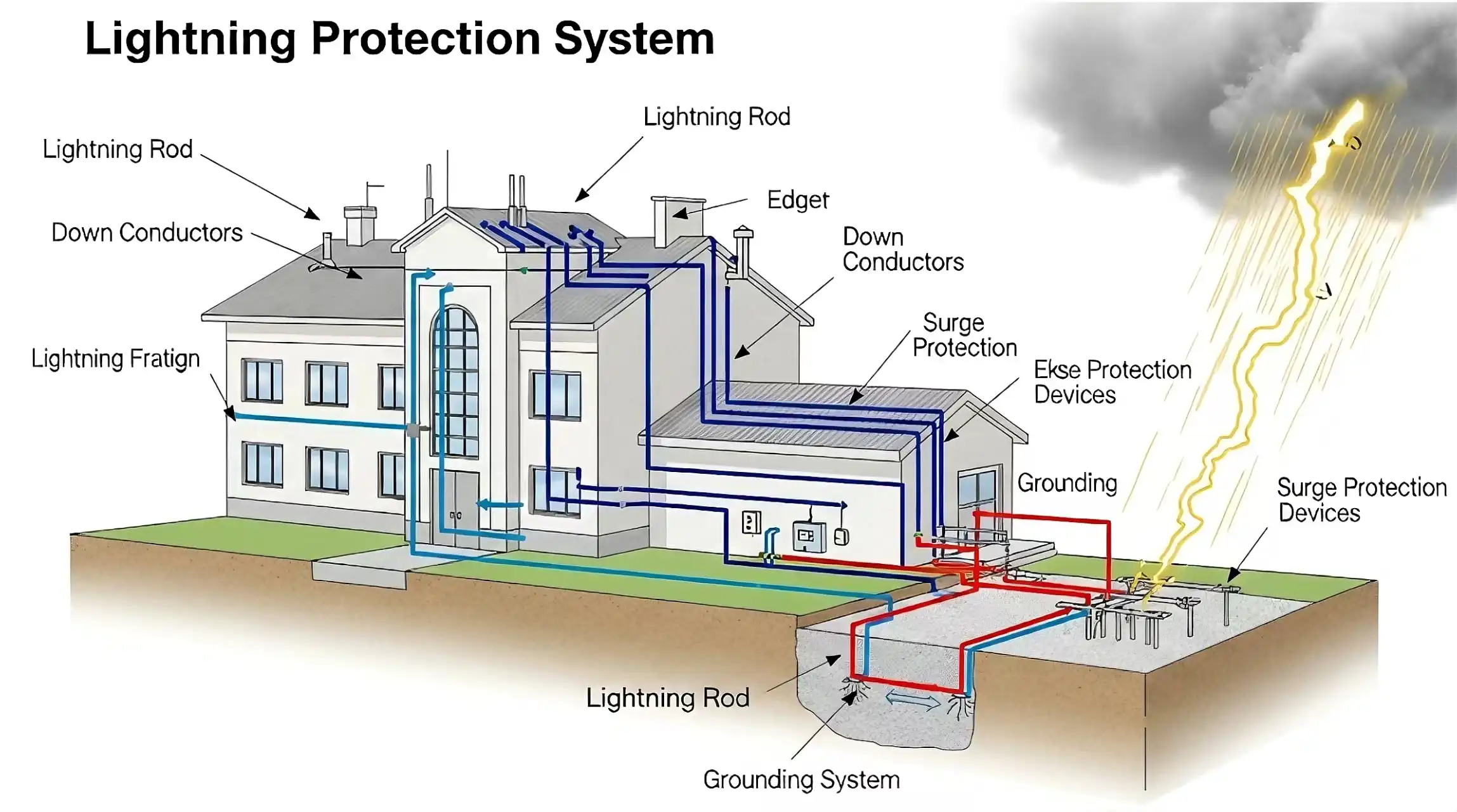
External LPS — Components & Design Logic
The external LPS comprises three interdependent components. All three must be correctly designed and installed — a deficiency in any one renders the entire system unreliable.
Air Termination System
The air termination system defines the attachment point — where the lightning strike terminates. For ESE systems, this is the terminal tip. The terminal must be positioned such that its protection radius covers all points of the structure to be protected, including roof-mounted equipment, parapets and any conductive protrusions above the roofline.
Per NFC 17-102, the ESE lightning rod must be installed at a minimum height of 2m above the highest point of the protected structure. ORBITAL recommends 4–6m for most industrial and commercial installations to maximise the protection radius Rp. See the ESE Protection Levels page for the full Rp calculation table.
Down Conductor System
Down conductors carry the intercepted lightning current from the air termination to the earth termination. IEC 62305-3 specifies minimum cross-sections of 50mm² copper or 100mm² aluminium for natural down conductors integrated into the structure, and 16mm² copper for dedicated test conductors. The routing must minimise bends and loops — sharp bends create inductance that can cause flashover to adjacent metalwork.
For tall structures, multiple down conductors distributed around the perimeter are required. At ground level, each down conductor connects to the earth termination via a test joint — an accessible, disconnectable connection that allows the earthing resistance to be measured independently without removing the air termination.
Earth Termination System
The earth termination system dissipates the lightning current into the soil. The target earthing resistance is ≤10 Ω per IEC 62305-3, though lower values are required for critical facilities and high soil-resistivity locations. ORBITAL's earthing product range — solid copper earth rods, copper-bonded rods, copper conductors and ORBetter® earthing enhancement compound — provides all components required to achieve the target resistance in any soil condition.
In high-resistivity soils (rocky terrain, sandy or dry conditions), achieving ≤10 Ω may require deep-driven rods, horizontal ring electrodes, or chemical treatment with ORBetter® compound to reduce contact resistance. The ORBetter® Earthing Enhancement Solution is specifically formulated for such conditions.
Internal LPS — Surge Protection & Equipotential Bonding
Even when an external LPS successfully intercepts a direct strike, the lightning current flowing through the down conductors and earthing system induces dangerous voltages in any conductive loop within the structure. These induced voltages — and the direct conduction of current through the earthing system — can damage or destroy all electrical and electronic equipment connected to the building's services.
The internal LPS prevents this through two mechanisms:
Equipotential Bonding
All conductive elements entering the structure — power cables, data lines, metallic pipes, structural steelwork, HVAC systems — are bonded to a common main equipotential bonding bar (MEB). This ensures that all elements rise to the same potential simultaneously during a lightning event, eliminating the potential difference that causes destructive arcing and current flow through sensitive equipment.
Surge Protective Devices (SPDs)
Service lines — power, data, telecommunications — cannot be directly bonded without interrupting their function. Instead, SPDs are installed in series with each line at the point of entry. SPDs clamp the transient overvoltage to a safe level, diverting the surge current to the bonding system.
IEC 62305-4 and IEC 61643-11 define three SPD types for coordinated protection:
Type 1 (Class I): Installed at the service entry point, typically in the main distribution board. Designed to handle direct lightning current components — up to 100 kA (10/350µs waveform). Required when the structure has an external LPS. Coordinated Type 1 devices are specified per network topology and risk assessment — see our surge protection range.
Type 2 (Class II): Installed at sub-distribution boards. Protects against switching surges and residual lightning transients not fully absorbed by the Type 1 device. 8/20µs waveform, up to 40 kA. Type 2 variants for single and three-phase boards are listed under surge protection devices.
Type 3 (Class III): Installed at the point of use — directly at sensitive equipment. Final layer of protection for equipment that cannot tolerate even the residual voltages passed through Types 1 and 2.
A critical point frequently overlooked: An external LPS without a coordinated internal SPD system is incomplete. The NFC 17-102 standard addresses only the external LPS. IEC 62305-4 governs the internal protection. Both are required for a compliant, fully protective installation. ORBITAL supplies both external and internal protection components and can design the complete coordinated system.
Applicable International Standards
A compliant lightning protection installation must reference the correct standards for each component. The following are the primary standards applicable to ORBITAL product installations:
Lightning Protection Zones (LPZ)
IEC 62305-4 introduces the Lightning Protection Zone (LPZ) concept as the framework for designing the internal LPS. The LPZ system defines a hierarchy of protected volumes, with each boundary representing a step-reduction in the lightning electromagnetic environment.
| Zone | Location | Threat Level | Protection Measure |
|---|---|---|---|
| LPZ 0A | Outside the structure, unprotected | Full direct strike and full electromagnetic field | External LPS (ESE lightning rod, down conductors, earthing) |
| LPZ 0B | Outside, within the ESE protection radius | No direct strike; full electromagnetic field | Protection provided by air termination system |
| LPZ 1 | Inside the building envelope | No direct strike; attenuated electromagnetic field; partial lightning current on service entries | Building shielding + Type 1 SPD at boundary |
| LPZ 2+ | Within shielded internal rooms / cabinets | Further attenuated electromagnetic field; residual surges only | Additional shielding + Type 2/3 SPD at each boundary |
SPDs must be installed at every LPZ boundary through which a service line passes. A power cable entering from LPZ 0A to LPZ 1 requires a Type 1 SPD; proceeding from LPZ 1 to LPZ 2 requires a Type 2; and at the equipment terminal within LPZ 2, a Type 3. This is the coordinated SPD protection concept — each device handles the portion of the surge appropriate to its rating and position.
System Design Procedure
A correctly designed lightning protection system follows a defined engineering sequence. Deviating from this sequence — for example, by selecting an ESE lightning rod before completing the risk assessment — invariably results in either over-specification (unnecessarily expensive) or under-specification (non-compliant and potentially dangerous).
Step 1 — Risk Assessment (IEC 62305-2 / NFC 17-102): Determine the expected annual strike frequency Nd and the tolerable frequency Nc for the structure. Calculate the required protection efficiency E = 1 − (Nc/Nd). Use our online Lightning Risk Calculator for a quick NFC 17-102 compliant assessment.
Step 2 — Protection Level Assignment: Map the calculated efficiency E to the corresponding NFC 17-102 protection level (I–IV). This determines the standard radius r (20/30/45/60m) and the minimum ESE ΔT requirement.
Step 3 — Air Termination Design: Select the ESE lightning rod(s) and mast height(s) to achieve the required Rp for all points of the structure. Verify coverage using the Rp formula. For large or complex structures, multiple ESE lightning rods with overlapping radii may be required.
Step 4 — Down Conductor Routing: Specify conductor cross-sections, routing path and number of down conductors. For structures taller than 20m, equidistant down conductors at a maximum spacing of 20m (LPL I/II) or 25m (LPL III/IV) are required.
Step 5 — Earth Termination Design: Determine the required earthing resistance, soil resistivity and electrode configuration. Specify rod lengths, burial depth and any enhancement measures needed.
Step 6 — Internal LPS Design: Map all service entries to the LPZ system. Specify SPD types, voltage protection levels (Up) and ratings for each boundary. Verify that the Up values at each stage are coordinated — each stage must present a lower Up than the previous.
Step 7 — Documentation: A compliant installation requires a technical file including the risk assessment calculation, system drawings, component data sheets with test certificates, and an installation and maintenance plan. ORBITAL provides full technical documentation for all supplied systems.
ORBITAL provides this entire process free of charge. Our engineers will conduct the risk assessment, design the complete system (external + internal LPS), specify all required components and prepare the technical documentation — for any project, any scale, anywhere in the world. Contact us to begin →