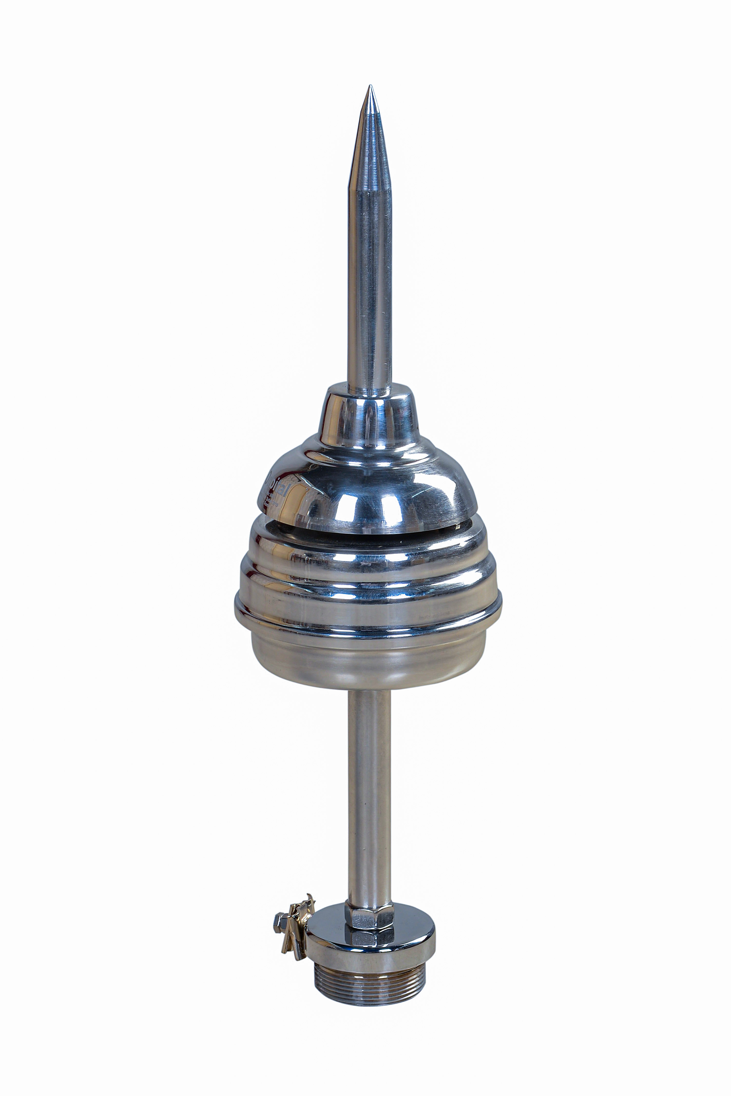

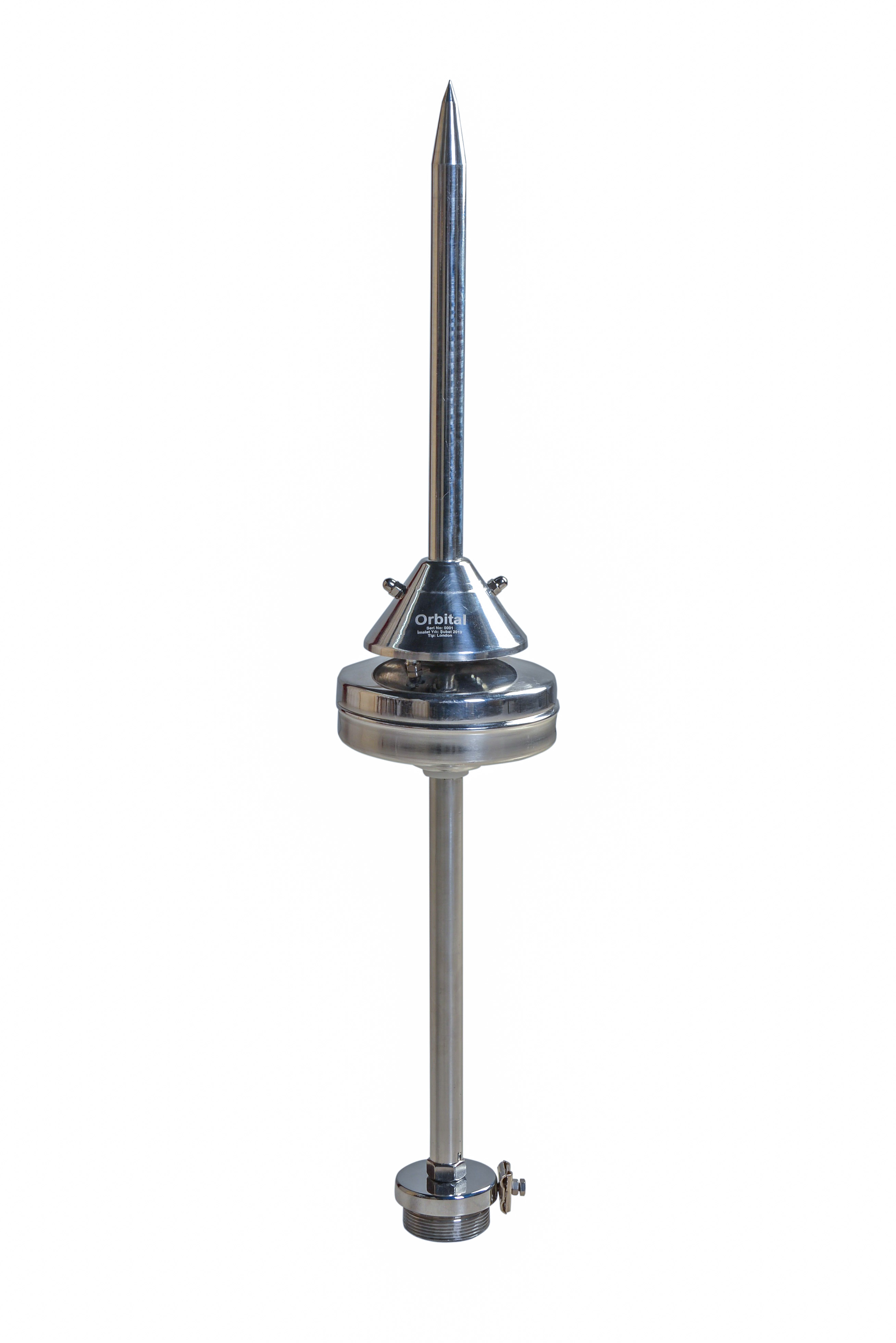
ORBITAL's highest-performance ESE active lightning rod. ΔT = 67µs, up to 107 metres protection radius, independently tested to 200kA. NFC 17-102:2011 certified. For airports, industrial plants, stadiums and critical infrastructure.
The HELIA is ORBITAL's highest-specification ESE active lightning rod. With a certified ΔT advance time of 67µs and an independently verified current withstanding capacity of 200kA, the HELIA provides the most comprehensive active lightning protection available from a single active lightning rod.
The active lightning rod operates through internal ion generation channels — a high-voltage impulse emitter combined with an electroatmospheric capacitor that detects the developing electric field of an approaching thunderstorm. As the field intensifies, the HELIA's mechanism activates, generating ionisation around the lightning rod tip that initiates an upward leader earlier than any competing structure within the protection radius.
The HELIA requires no external power source, no batteries and no electronic control unit. It is entirely autonomous — once correctly installed, it operates indefinitely with only periodic inspection. All components are manufactured from 304L inox stainless steel, ensuring reliable performance in marine, industrial and tropical environments.
Independent certification: The HELIA's ΔT value was verified by METU (Middle East Technical University) laboratory — an accredited NFC 17-102 test facility. Current withstanding tests conducted at HIZAL Lightning Test Lab. Full test reports available on request. Contact ORBITAL →
| Electrical Performance | |
| Advance Time (ΔT) | 67 µs — certified per NFC 17-102 Annex C test |
| Peak Current Withstanding | 200 kA (10/350µs waveform) — 2× NFC 17-102 minimum |
| Operating Principle | Ion generation — electroatmospheric capacitor + high-voltage impulse emitter |
| Protection Levels | Level I (98%), Level II (95%), Level III (90%), Level IV (80%) |
| Power Source | None — fully autonomous, powered by atmospheric electric field |
| Mechanical & Environmental | |
| Construction Material | 304L Inox Stainless Steel — all external components |
| Operating Temperature | −40°C to +85°C |
| Ingress Protection | IP67 |
| Wind Resistance | Tested to 220 km/h |
| Min. Installation Height | 2m above highest point of protected structure (NFC 17-102 minimum) |
| Recommended Height | 4–6m for optimal Rp |
| Compliance & Certification | |
| Primary Standard | NFC 17-102:2011 — Early Streamer Emission |
| CE Marking | Yes — Declaration of Conformity available upon request |
| ΔT Test Laboratory | METU (Middle East Technical University), Turkey — accredited |
| Current Test Laboratory | HIZAL Lightning Test Lab, Turkey — accredited |
| Quality Management | ISO 9001:2015 |
| Compatibility | |
| Down Conductors | Tape/strip, round conductor, insulated HVSC cable — all standard types |
| Test Equipment | ORBITAL ORB-ONE ESE Test Unit, ORB-X Strike Counter Test Unit |
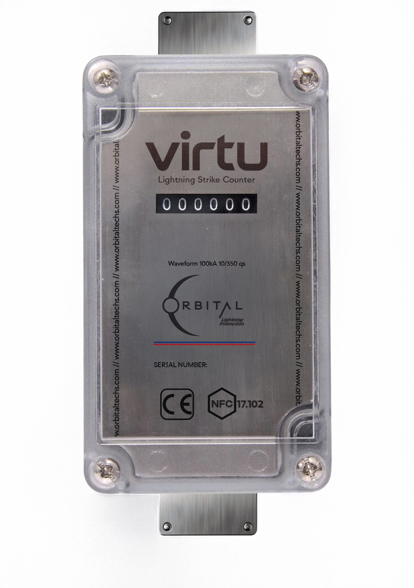
| Strike Counters | VIRTU and STELLAR (all ORBITAL series) |
| Warranty | 20 years |
Protection radius Rp calculated per NFC 17-102 formula: Rp = √[h(2r − h) + ΔT(2r + ΔT)]
h = mast height above structure · r = standard radius per level · ΔT = 67µs (HELIA certified value)
| Height (m) | Level 1 — r=20m Protection Radius (m) |
Level 2 — r=30m Protection Radius (m) |
Level 3 — r=45m Protection Radius (m) |
Level 4 — r=60m Protection Radius (m) |
|---|---|---|---|---|
| 2 | 85 | 93 | 103 | 113 |
| 3 | 85 | 93 | 104 | 113 |
| 4 | 86 | 93 | 104 | 114 |
| 5 | 86 | 94 | 105 | 114 |
| 6 | 86 | 94 | 105 | 115 |
| 8 | 86 | 94 | 106 | 116 |
| 10 | 86 | 95 | 106 | 117 |
| 15 | 87 | 96 | 108 | 119 |
107m is the maximum protection radius recognised under NFC 17-102 regardless of calculated value. For project-specific calculations use the ORBITAL Risk Calculator or contact our engineers.