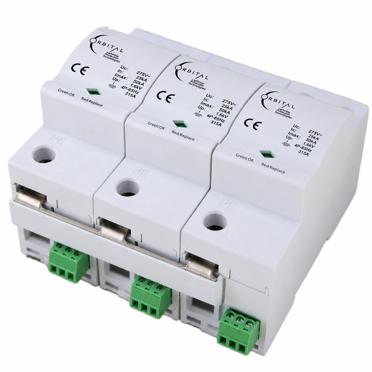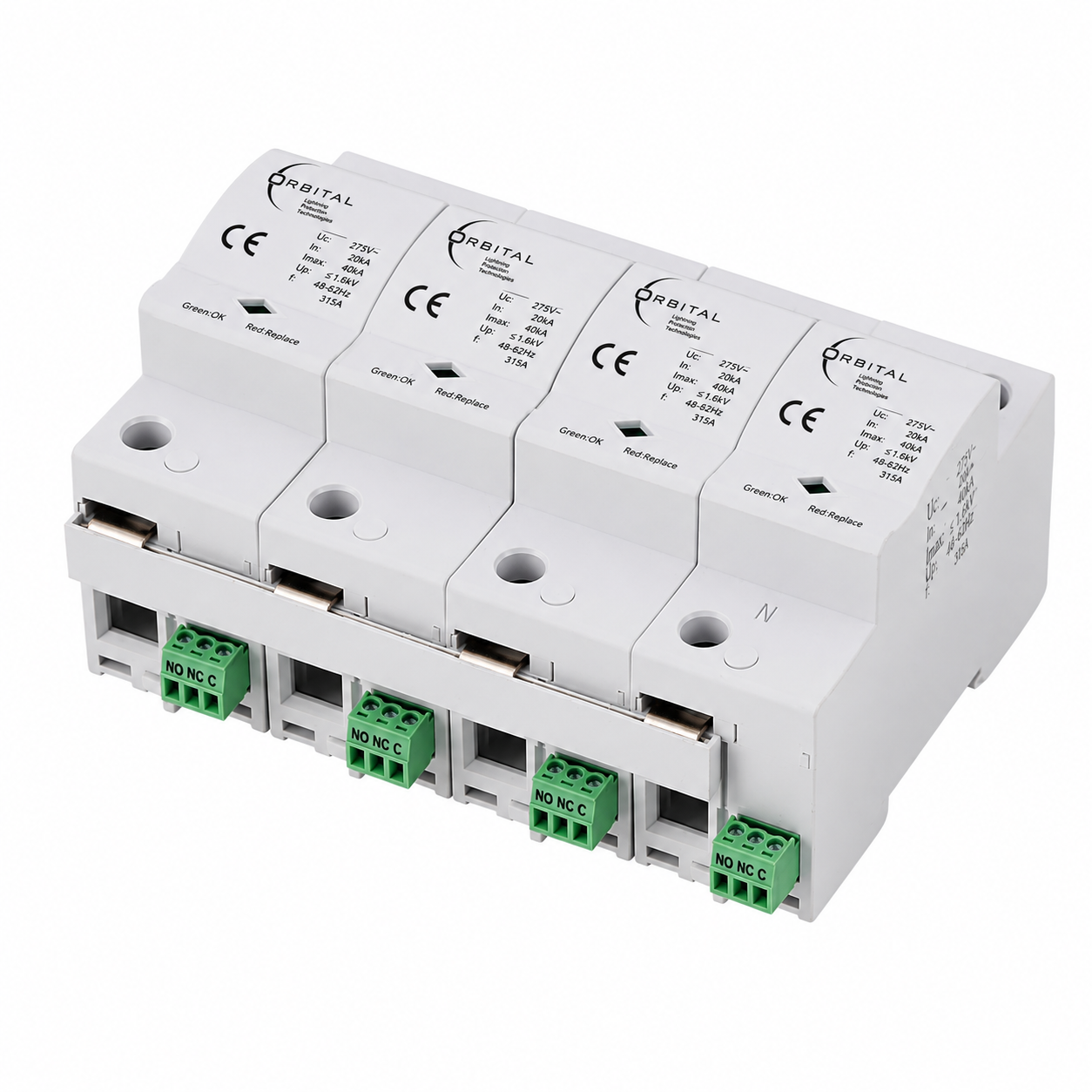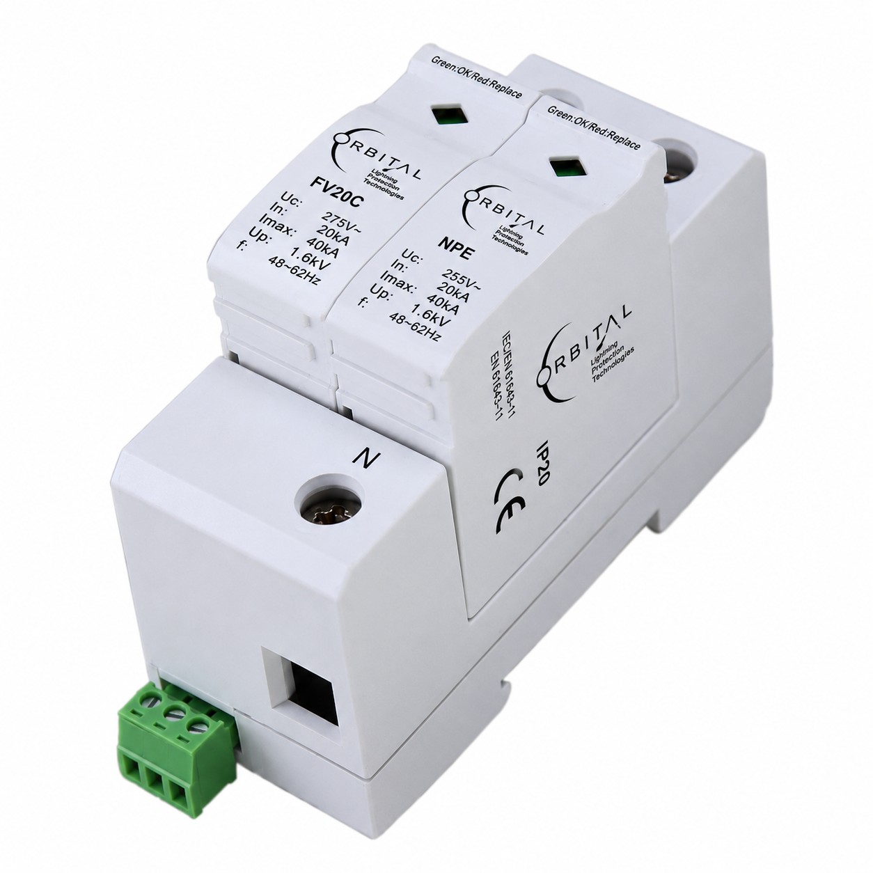
AC surge protective device for low-voltage distribution — 1 pole + NPE, TT network, protection modes L–N and N–PE. Thermo-dynamic disconnector, mechanical fault window and remote signalling.
OSPD 101 is ORBITAL's catalogue designation for a Type 2 / Class II surge protective device in a 1P+N (single-phase + NPE) topology for TT low-voltage networks. It is positioned in the LPZ 1–2 boundary concept to limit lightning and switching transients before they propagate toward sensitive loads.
The protection modes cover L–N and N–PE. High-energy sections rely on metal oxide varistor (MOV) technology with a thermo-dynamic disconnector that safely disconnects degraded modules. A mechanical inspection window gives clear status (green: OK · red: replace), and remote signalling contacts allow integration into monitoring systems.
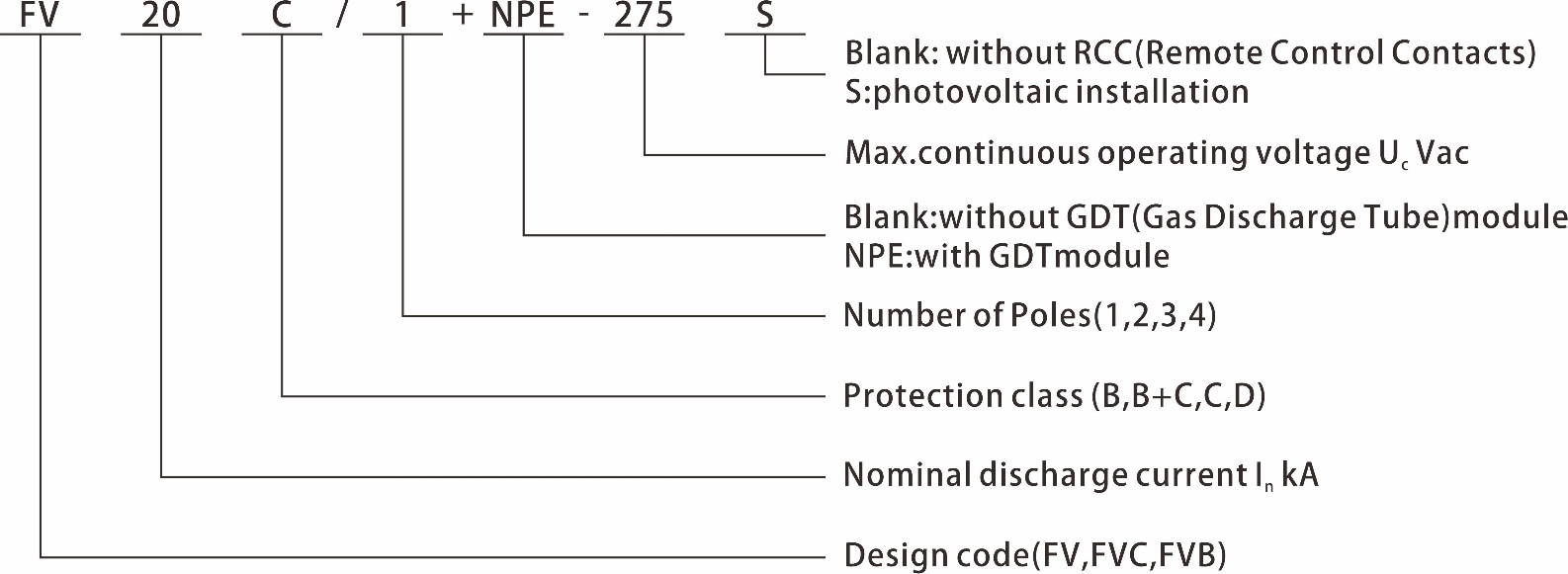
Technical correspondence: Electrical architecture matches reference catalogue type FV20C/1+NPE-275S (manufacturer listing). The coding diagram in the Technical tab is shown for installer reference alongside the parameter table.
The Coding diagram is shown below, followed by the full Electrical parameters table.
| Electrical parameters | |
| Model designation | FV20C/1+NPE-275S (reference base) |
| SPD protection standard | IEC 61643-11 / EN 61643-11 — Type 2 |
| SPD installation type standard | IEC 61643-11 / EN 61643-11 — Class II |
| Protection level (VDE) | DIN VDE 0675-6 — Class C |
| Type of network | TT |
| Protection mode | L–N , N–PE |
| Nominal voltage Un | 220/380 Vac · 50/60 Hz |
| Maximum continuous operating voltage Uc | 275 Vac · 50/60 Hz |
| Continuous operating current IC | < 20 µA |
| Residual current IPE | ≤ 20 µA dc · ≤ 500 µA ac |
| Standby power consumption PC | ≤ 25 mVA |
| Maximum discharge current Imax (8/20 µs) | 40 kA |
| Nominal discharge current In (8/20 µs) | 20 kA |
| Voltage protection level Up — L–N | ≤ 1.2 kV |
| Voltage protection level Up — N–PE | ≤ 1.5 kV |
| Isolation resistance Risol | > 1000 MΩ |
| Response time tA — L–N | ≤ 25 ns |
| Response time tA — N–PE | ≤ 1000 ns |
| Remote control contact | Yes |
| Disconnection indicator | Mechanical — green OK / red replace |
| Mechanical & environmental | |
| I/O connections | Screw terminal 10–35 mm² · connection bus option |
| Installation location | Inside |
| Mounting type | Symmetrical DIN rail (EN 50022 / DIN 46277-3) |
| Colour | Grey |
| Degree of protection | IP20 |
| Housing material | UL94 V-0 |
| Ambient temperature | −40°C · +80°C |
| Altitude | ≤ 2000 m amsl |
| Permissible humidity | 30%–90% |
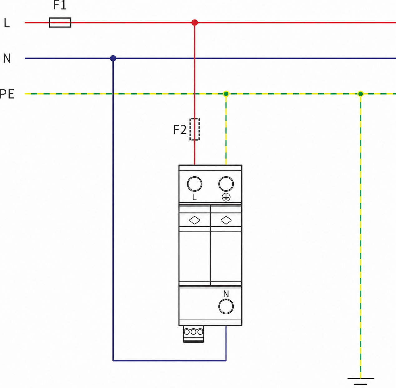
Typical panel mounting — retain conductor sizing, torque values and clearances per project drawings.