

The Function of a Lightning Protection System
The main function of a lightning strike protection system installed on a building is to capture a lightning stroke and conduct the current safely to earth. A complete external lightning protection system (LPS) is normally designed in line with IEC 62305 and, for ESE installations, NFC 17-102 — covering air terminals, down conductors, earthing and equipotential bonding. See our guide to how a full lightning protection system is structured.
In many situations, however, an ESE active lightning rod is the most practical way to protect a structure from direct strikes — especially when a conventional Franklin layout would need many rods, complex roof routing, or cannot meet the required protection radius economically.
We recommend ESE systems whenever the passive solution becomes inconvenient or insufficient: large footprints, industrial halls, logistics centres, airports, telecom sites and other structures where a single mast can cover a wide area. For sector-specific layouts, see ESE applications by industry.
Key Principle: The lightning discharge always follows the path of least resistance. An ESE lightning rod artificially creates the most attractive path, intercepting the strike before it reaches the structure.
How Does an ESE Lightning Rod Work?
The lightning discharge process is initiated by a downward leader — an ionised air channel that propagates downward from the storm cloud toward earth. In response, structures and conductive objects generate upward streamers competing to intercept this leader.
An ORBITAL ESE lightning rod uses two armatures: one bonded to earth and one at atmospheric potential. The potential difference across this arrangement powers the internal Variable Impedance Unit, which responds to the atmospheric electric field — the same principle described in NFC 17-102 for early streamer emission devices.
Under fair weather the unit stays inactive, so components are not stressed unnecessarily. When a storm approaches and the field rises sharply, the device activates. Internal ion generation at the tip increases local ionisation; the resulting streamer effect produces upward leaders that propagate toward the descending strike much earlier than on a passive rod.
Inside the device, equi-potential lines concentrate charge on the armature surface. The ionised volume at the tip therefore grows much faster than with a simple conventional rod, improving the probability that the ESE becomes the preferred interception point. One streamer becomes the dominant upward leader, completing the discharge path so the current is conducted safely to earth through the down conductor and earthing system.
Operation is fully autonomous — no external power supply is required. ORBITAL ESE lightning rods are built in stainless steel (304L), tested to withstand impulse currents up to 200 kA (10/350 µs), and supplied ready for integration with strike counters and periodic inspection as required by the standard.
ESE vs. Conventional Lightning Rods
The fundamental difference between an ESE and a passive Franklin rod begins the moment storm clouds form. While a conventional rod waits passively, an ESE lightning rod actively prepares to intercept the incoming discharge. For a longer comparison of both philosophies, read passive vs active lightning protection.
| Characteristic | ESE Lightning Rod | Conventional Rod |
|---|---|---|
| Operating principle | Active — generates ionisation | Passive — waits for strike |
| Protection radius | Up to 107 metres | Up to ~30 metres |
| Large area coverage | Single unit covers wide area | Multiple units required |
| Response to storm | Activates before strike | Reacts only on impact |
| Applicable standard | NFC 17-102, IEC 62305 | IEC 62305, EN 50164 |
| Maintenance | Periodic inspection | Minimal |
| Best for | Large structures, industrial, airports | Small buildings, chimneys |
The ΔT (Delta-T) Value — Advance Time
The protected area of an ESE installation is defined by the advance time (ΔT) — how many microseconds earlier the ESE initiates an upward streamer than a conventional rod of the same height under identical test conditions. A higher certified ΔT means a larger effective protection radius Rp for the same mast height and protection level.
Under NFC 17-102:2011, a device must demonstrate ΔT between 10 and 60 microseconds in an accredited laboratory to be marketed as an ESE lightning rod. ORBITAL rods are independently tested at several ΔT values; the declared level must match the product documentation and nameplate. More on the standard in our article NFC 17-102 and ESE certification.
Protection Radius Formula (NFC 17-102):
Rp = √[h(2r − h) + ΔT(2r + ΔT)]
Where h = height of the ESE tip above the reference plane, r = standard radius for the assigned protection level (I–IV), and ΔT = advance time in microseconds. Full level definitions and case studies are on the ESE protection levels page.
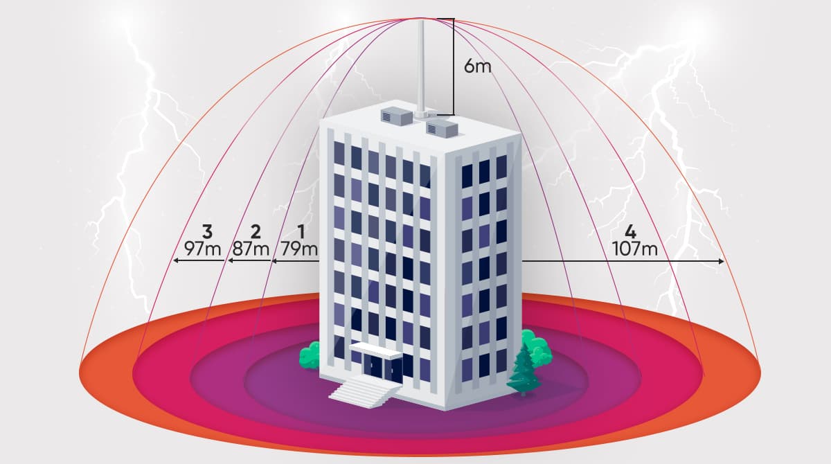
Illustration: how protection radius expands with NFC 17-102 protection level when an ESE lightning rod is installed 6 m above the structure (example radii for a certified ORBITAL ESE — always verify Rp for your project using mast height, level and product ΔT).
Before installation, assign the structure a protection level (I–IV) from the risk assessment. The table below shows typical Rp values at h = 6 m for a high-performance ESE; your project may differ if height, level or product ΔT changes.
| Protection level | Typical Rp at h = 6 m | Minimum efficiency (NFC 17-102) |
|---|---|---|
| Level I — very high risk | 79 m | 98% |
| Level II — high risk | 87 m | 95% |
| Level III — medium risk | 97 m | 90% |
| Level IV — standard | 107 m | 80% |
When Should You Use an ESE System?
ESE protection is particularly suited to the following scenarios (see also ESE FAQ):
Large surface area structures — industrial plants, warehouses, logistics centres and airports where a single ESE lightning rod can replace multiple conventional rods. Browse real-world layouts on applications by sector.
Buildings where conventional rods cannot be installed — heritage sites, aesthetic constraints, or roofs where multiple penetrations are undesirable.
High-risk or critical infrastructure — telecom towers, fuel storage, hospitals and data centres where a direct strike has severe consequences.
Areas with high lightning density — regions with Ng above 2.5 strikes/km²/year. Use the lightning risk calculator to estimate required protection level before selecting rod height and ΔT.
ORBITAL ESE Lightning Rods
ORBITAL manufactures a complete range of ESE lightning rods — COMET, ZERU, HELIA and CONTRA (CESE) series — for different protection levels and project scales. All are tested and certified to NFC 17-102 and CE requirements. Explore the full external lightning protection range, including down conductors, earthing and strike counters for maintenance records.
Use our risk calculator to estimate protection level and ESE radius for your site, or contact our engineering team for a free technical assessment.