

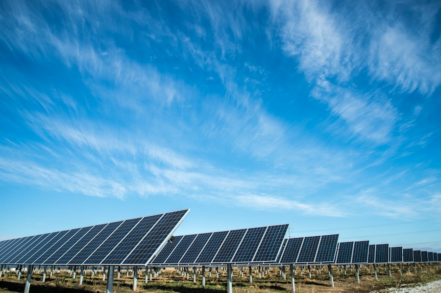
Why Solar Farms Are High Risk
A solar farm concentrates several factors that maximise lightning exposure: large conductive areas at moderate height above flat, open terrain; extensive metallic framing structures directly connected to sensitive power electronics; and kilometres of DC and AC cabling running through areas with no natural shielding.
The financial consequences of a lightning strike on an unprotected solar installation are severe. A single return stroke can destroy multiple inverters (each costing €5,000–€50,000), damage or destroy hundreds of panels, ignite fires in combiner boxes, and take the installation offline for weeks or months while repairs are made and insurance claims are processed. Project financiers and insurers increasingly require a certified lightning protection system as a condition of financing and coverage.
The Standard Approach — and Its Limitations
Many solar farm installations rely on the panel framing structure itself for lightning protection — assuming that the metallic frames, connected to earth via the array mounting system, will attract and conduct lightning strikes. This approach has two critical flaws.
First, the panel framing is directly connected to the DC wiring and inverter inputs. A strike that terminates on the framing injects current directly into the DC circuit — destroying the inverters and potentially igniting the cable runs. A properly designed air termination system must intercept the strike above the panels, not at frame level.
Second, the earthing resistance of a typical solar array mounting system — driven by the number and depth of anchor posts — is rarely verified to meet the ≤10 Ω target of IEC 62305-3. In rocky or dry soils, the actual resistance may be orders of magnitude higher, rendering the earthing system ineffective.
The Correct Approach — ESE Active Lightning Rods Above the Array
A correctly designed solar farm LPS mounts ESE active lightning rods on dedicated masts positioned to provide a protection radius that covers the entire array area, with the lightning rod tip above the highest point of the panel surface. The NFC 17-102 protection radius formula is used to determine the number and positioning of active lightning rods.
For a typical utility-scale solar farm, COMET ESE Lightning Rods on 6–8m masts at 100–150m spacing provide efficient coverage while minimising shading impact on the panels below. The masts are positioned between panel rows and do not penetrate any panel structure.
DC and AC Surge Protection
Even with a well-designed external LPS, lightning-induced surges on the DC string circuits and AC output cables remain a significant hazard. Every string combiner box requires DC SPDs rated for the maximum system voltage (typically 1000–1500V DC). The AC inverter outputs and the grid connection point require coordinated AC SPDs.
ORBITAL's OSPD surge protection devices cover the AC protection requirements. For DC string protection, the specific requirements depend on system voltage and configuration — our engineers will specify the correct devices for your installation.
Earthing the Solar Farm
The earthing system for a solar farm serves multiple functions: lightning current dissipation, equipment safety earthing, and functional earthing for inverter operation. A single earthing network serves all three, but the design must meet the most stringent requirement — typically ≤10 Ω for lightning protection, with continuous ring conductors connecting all array sections and individual earth electrodes at regular intervals.
In sites with high soil resistivity — common in arid or rocky terrain where solar farms are often located — achieving ≤10 Ω may require the use of ORBetter® Earthing Enhancement Compound around the electrodes to reduce contact resistance and maintain stable performance across seasonal moisture variations.