

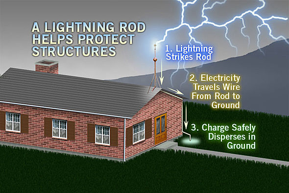
Method 1 — The Franklin Rod (Conventional Lightning Rod)
Invented by Benjamin Franklin in 1752, the conventional lightning rod is the oldest and most widely used lightning protection method in the world. It consists of a pointed copper or stainless steel rod mounted at the highest point of a structure, connected to earth via a down conductor and earthing electrode.
The rod works by creating a local enhancement of the electric field at its tip. When a lightning downward leader approaches, this field enhancement makes the rod a preferential attachment point — the strike terminates at the rod rather than elsewhere on the structure, and the current is safely conducted to earth.
The protection radius of a conventional rod is approximately equal to its installed height above the protected structure. A rod mounted 5m above a roofline protects a radius of roughly 5m. For a large structure, this requires multiple rods spaced across the roof — typically one every 10–15m for a Level III installation per IEC 62305-3.
Best for: Small residential buildings, isolated chimneys, water towers, small agricultural structures. Not practical for large industrial footprints without combining with a mesh system. See ORBITAL's Conventional Lightning Rods.
Method 2 — Faraday Cage / Mesh System
The Faraday cage method, also called the mesh method, covers the roof and walls of a structure with a network of conductors connected at regular intervals to multiple down conductors and earth electrodes. Rather than creating a single preferential attachment point, the mesh creates a conductive "cage" that makes the entire structure an attractive target — then safely disperses the current through the extensive conductor network to earth.
Per IEC 62305-3, the mesh size is determined by the protection level: 5m × 5m for Level I, 10m × 10m for Level II, 15m × 15m for Level III, and 20m × 20m for Level IV. Down conductors must be spaced at 10m (Level I/II) or 20m (Level III/IV) intervals around the building perimeter.
The Faraday cage method provides uniform coverage regardless of roof geometry and is the standard method for protecting flat-roofed industrial buildings and structures where the rooftop surface must be fully protected. The main disadvantage is the extensive civil works required — dozens of conductor fixings, multiple roof penetrations and a complex earthing network.
Best for: Large flat-roofed industrial buildings, data centres, substations where the entire roof surface must be protected. Often combined with ESE lightning rods at high points. See our Faraday Cage Application.
Method 3 — ESE Active Lightning Rod
The ESE (Early Streamer Emission) active lightning rod is the most technologically advanced method available under current international standards. An internal mechanism detects the developing electric field of an approaching storm and generates ionisation around the lightning rod tip, producing an upward leader that travels toward the downward leader earlier than any competing structure.
This advance time — the ΔT value — extends the lightning rod's protection radius dramatically beyond what a passive rod could achieve at the same height. A single ORBITAL HELIA ESE Lightning Rod at 6m mast height provides a calculated protection radius of up to 107m under NFC 17-102 — replacing what would require 10 or more conventional rods on a large industrial structure.
ESE lightning rods are governed by NFC 17-102 and IEC 62305, and must be independently tested and certified to confirmed ΔT values. ORBITAL lightning rods are tested and certified to NFC 17-102:2011 and carry CE marking.
Best for: Industrial plants, airports, solar farms, stadiums, hospitals, telecom infrastructure and any large structure where minimising installation complexity while maximising coverage is the priority. Read the full ESE technical guide →
Method 4 — Charge Dissipation Arrays (CDA)
Charge dissipation arrays work on a different principle: rather than attracting and intercepting a lightning strike, they attempt to prevent the strike from forming by bleeding charge from the structure into the surrounding air, reducing the potential difference that drives the discharge.
In theory, if the local electric field at the structure can be kept below the threshold for upward leader formation, the lightning will discharge elsewhere. In practice, the effectiveness of CDA systems is highly contested. Neither IEC 62305 nor NFC 17-102 recognises CDA as an approved lightning protection method — there is no standardised test procedure, no defined protection radius, and the peer-reviewed field data does not support the performance claims made by manufacturers.
ORBITAL does not manufacture or recommend CDA systems. For structures where an external protection system must demonstrably comply with international standards — as required for insurance, regulatory approval and liability purposes — only methods covered by IEC 62305 or NFC 17-102 are appropriate.
Choosing the Right Method
In practice, the best installations often combine methods: ESE lightning rods at the highest exposed points with a partial Faraday mesh to protect lower roof areas, all tied to a common earthing system with surge protection devices (SPDs) on all service entries. The choice depends on the structure geometry, required protection level, installation constraints and budget.
Use the ORBITAL Lightning Risk Calculator to determine the required protection level for your structure, or contact our engineers for a complete system design — free of charge.