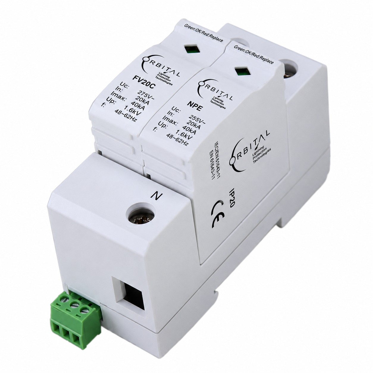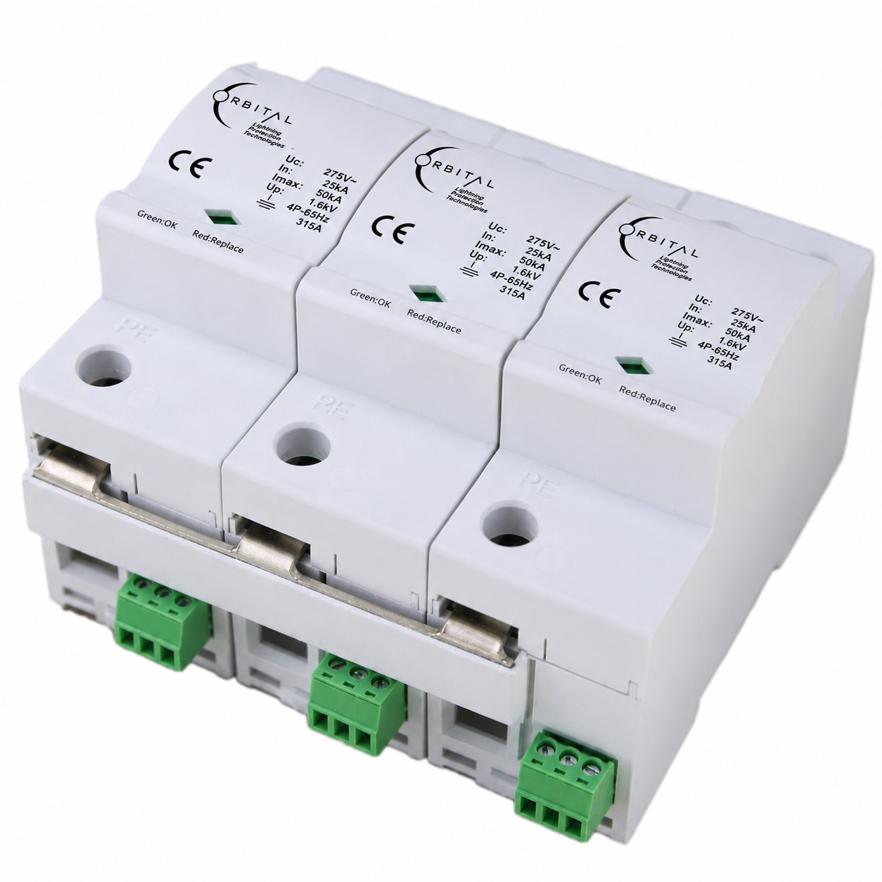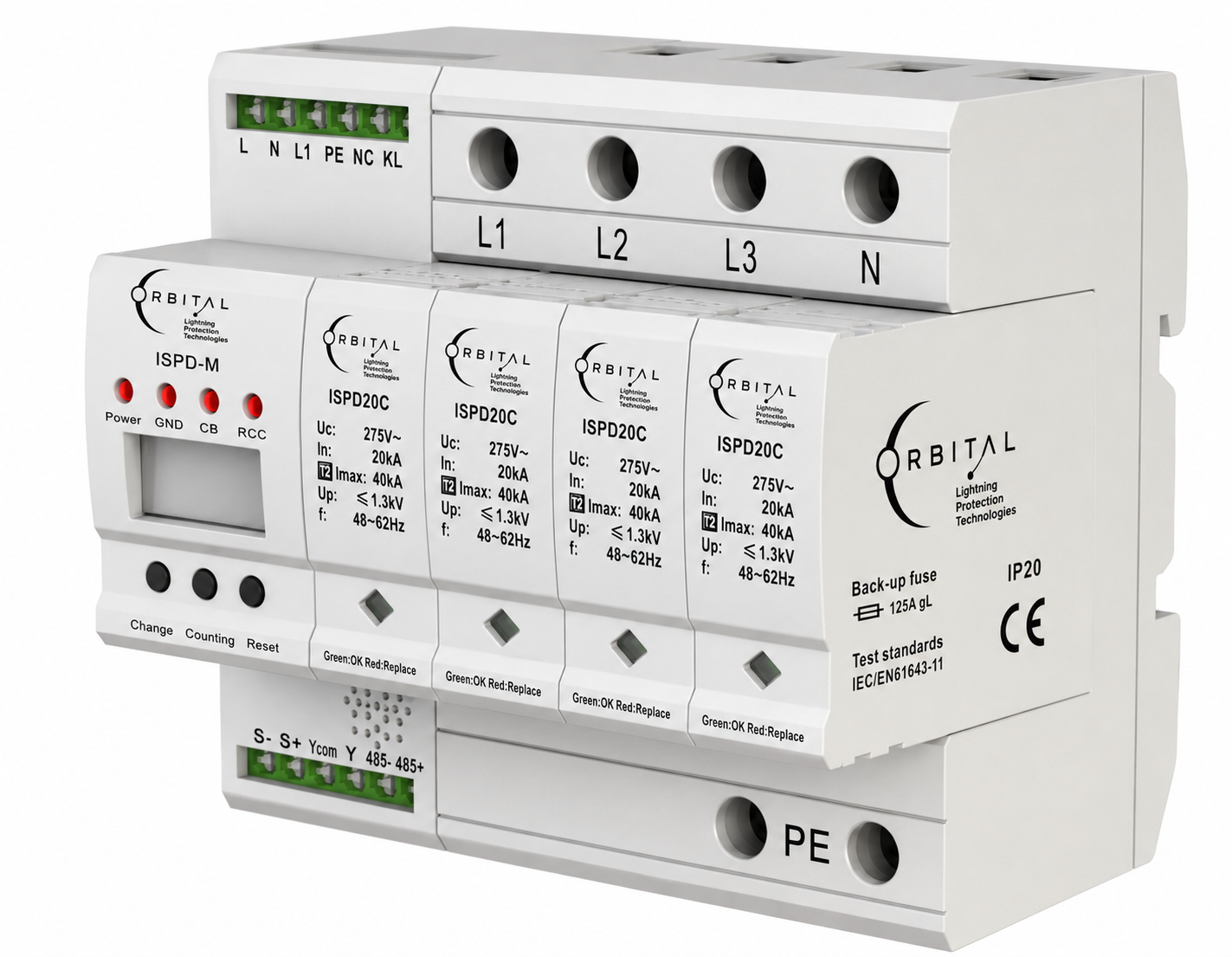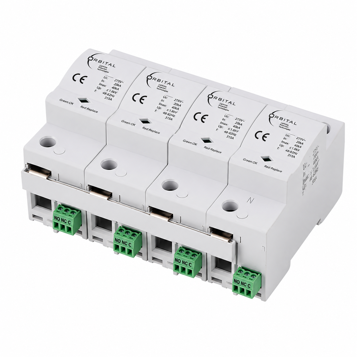
AC surge arrester for low-voltage distribution — Class B+C / Type 1+2 (I+II), 3P+N for TT networks at the LPZ 0–1 boundary. High-energy MOV cores with thermo-dynamic disconnector, fault window and remote signalling.
OSPD 404 is ORBITAL's catalogue designation for a Type 1+2 / Class I+II (B+C) surge arrester in 3P+N form for TT low-voltage networks. It is intended for the LPZ 0–1 lightning protection zone boundary — where direct or very high-energy surge threats must be clipped before energy propagates into internal installation zones.
Published protection modes cover L1, L2, L3–N and N–PE. The design uses high discharge-capacity metal oxide varistor (MOV) cores with a thermo-dynamic control disconnector, mechanical status window (green: OK · red: replace) and remote signalling for supervisory integration.
Technical documentation: Electrical architecture follows IEC/EN 61643-11 Type 1+2 (Class I+II) practice for this 3P+N TT topology. Dimension, wiring and parameter tables on this page reflect our approved datasheet; CAD-ready excerpts ship with quotations on request.
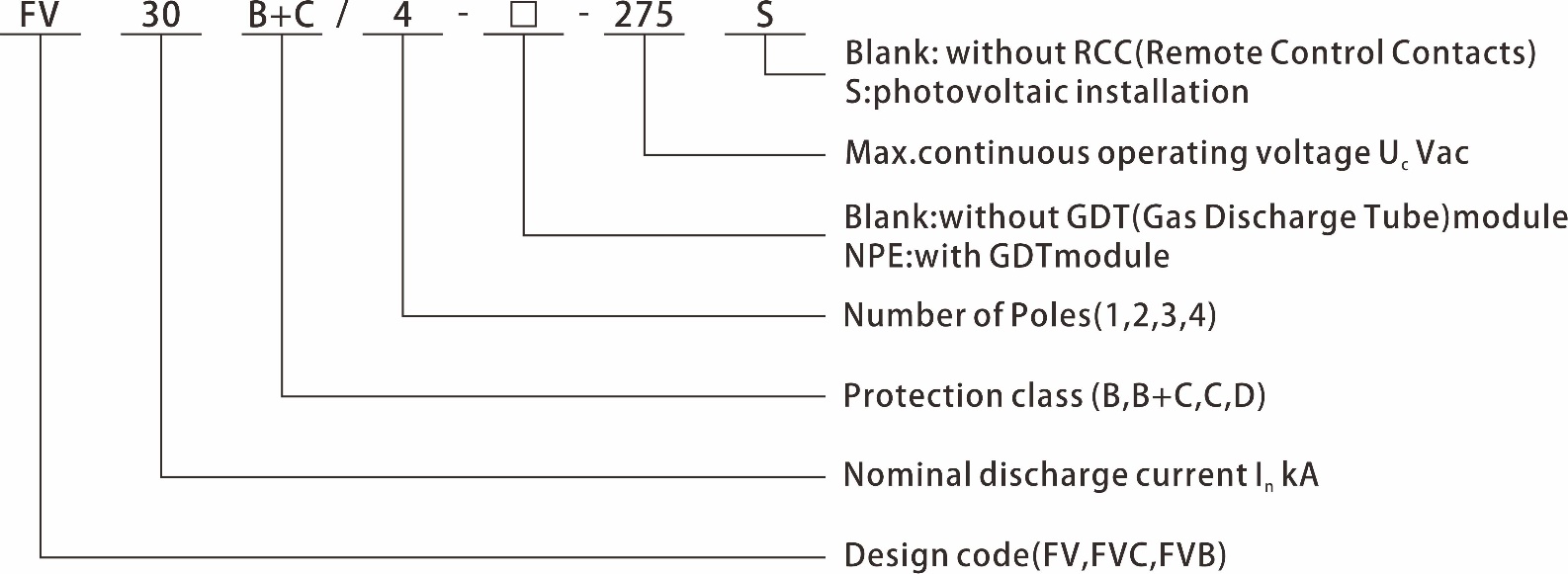
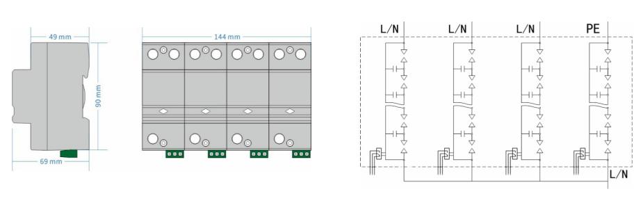
Model coding, dimensions and internal circuit graphics illustrate the product construction. Electrical parameters in the table summarise the approved datasheet.
| Electrical parameters | |
| Model designation | OSPD 404 · equivalent industry designation FV25B/3+NPE family (variant suffix per order code) |
| SPD protection standard | IEC 61643-11 / EN 61643-11 — Type 1+2 |
| SPD installation type standard | IEC 61643-11 / EN 61643-11 — Class I+II |
| Protection level (VDE) | DIN VDE 0675-6 — Class B |
| Type of network | TT |
| Protection mode | L1, L2, L3–N · N–PE |
| Nominal voltage Un | 220/380 Vac · 50/60 Hz |
| Maximum continuous operating voltage Uc | 275 Vac · 50/60 Hz |
| Short-circuit withstand capability Isccr | 25 kA |
| Continuous operating current IC | < 20 µA |
| Rated load current IL | 315 A |
| Residual current IPE | ≤ 20 µA dc · ≤ 500 µA ac |
| Standby power consumption PC | ≤ 25 mVA |
| Follow current extinguish capability Ifi — L–N | ≥ 25 kArms |
| Follow current extinguish capability Ifi — N–PE | ≥ 100 Arms |
| Nominal discharge current In (8/20 µs) — L–N | ≥ 25 kA |
| Nominal discharge current In (8/20 µs) — N–PE | ≥ 100 kA |
| Impulse discharge current Iimp (10/350 µs) — L–N | ≥ 25 kA |
| Impulse discharge current Iimp (10/350 µs) — N–PE | ≥ 100 kA |
| Voltage protection level Up | ≤ 1.5 kV |
| Isolation resistance Risol | > 1000 MΩ |
| Response time tA | ≤ 100 ns |
| Energy let-through note | Remaining energy after operation < 151 J (coordination test context per datasheet) |
| Temporary overvoltage UTOV | ≥ 440 V (±1%) / 120 min |
| Remote control contact | Yes |
| Disconnection indicator | Mechanical — green OK / red replace |
| Mechanical & environmental | |
| I/O connections | Screw terminal 10–35 mm² · connection bus option |
| Installation location | Inside |
| Mounting type | Symmetrical DIN rail (EN 50022 / DIN 46277-3) |
| Colour | Grey |
| Degree of protection | IP20 |
| Housing material | UL94 V-0 |
| Ambient temperature | −40°C · +80°C |
| Altitude | ≤ 2000 m amsl |
| Permissible humidity | 30%–90% |
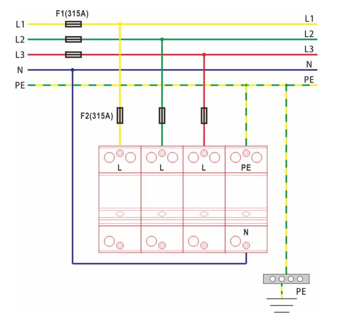
Typical TT application schematic — retain fuse ratings, conductor sizing and torque per final project drawings.